
7. Theory of operation#
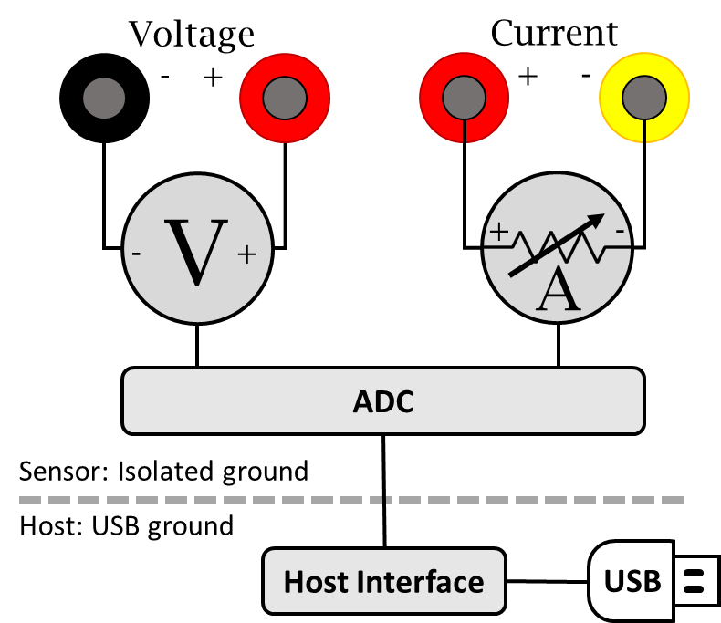
Joulescope simultaneously measures current and voltage, and then computes power and energy. Joulescope combines a voltmeter and a fast auto-range current shunt ammeter.
7.1. Ammeter#
The shunt ammeter consists of six (6) current ranges with six (6) different shunt resistor values ranging from 0.01 Ω to 1111 Ω. Joulescope actively selects the best shunt resistor to keep the maximum voltage across the shunt resistor to 20 mV. This low voltage drop minimizes the impact on the device under test. Other equipment, including standard multimeters, have a much larger burden voltage that can cause the target device to behave unusually.
The Joulescope amplifies the voltage across the shunt resistor and then uses an analog-to-digital converter (ADC) to digitize the value. The ADC digitizes the value 2 million times per second to create 2 million samples per second (SPS). The Joulescope instrument processes these ADC values on the instrument using a sensor-side FPGA.
Given a known resistor value and the measured voltage, the Joulescope uses Ohm’s Law to compute current. The FPGA applies calibration coefficients to convert the measured voltage into the measured current. Joulescopes are individually calibrated and tested in the factory to ensure that every Joulescope performs to specification.
The instrument then downsamples by 2 from 2 Msps to 1 Msps. This downsampling saves USB bandwidth without affecting the measurement bandwidth.
7.1.1. Autoranging#
As the current changes, the ammeter selects the optimal shunt resistor value. Joulescope uses dedicated hardware to quickly select the appropriate shunt resistor to avoid impacting the device under test. The shunt value selection uses the ADC output, dedicated over-range analog hardware, and a unique algorithm that runs in an FPGA. The FPGA selects the active shunt resistors using MOSFETs, which were carefully qualified to meet Joulescope’s demanding performance characteristics.
The shunt resistor selection does take some time. How fast does the shunt resistor need to change to have a minimal impact? The linearized equation is:
t = C * ΔV / ΔI
Let’s take a typical example. The target device takes 3.3V and can tolerate a temporary 3% (0.03) voltage glitch on a 1 amp change. If the target device has 10 μF of capacitance, the required shunt resistor switching time is approximately:
10 μF * 3.3 V * 0.03 / 1 A = 1 μs
Joulescope was designed to achieve 1 µs switching speed to meet this demanding case. Most target systems have larger capacitance and less dramatic step current changes. In all cases, the shunt resistor selection is always make-before-break to ensure uninterrupted connectivity to the target device.
7.1.2. Current ranges#
Embedded devices span a very wide current range. A wireless sensor may sleep at tens to hundreds of nA, then wake and transmit at tens to hundreds of mA. Other targets draw several amperes. Joulescope covers nA to 10 A, approximately 10 decades, which no single shunt resistor and ADC can resolve with adequate accuracy.
The JS320 has six current ranges. The settings below identify each range by its index:
Index |
Range |
|---|---|
0 |
10 A |
1 |
180 mA |
2 |
18 mA |
3 |
1.8 mA |
4 |
180 µA |
5 |
18 µA |
Autoranging selects the most sensitive range that does not overflow. When the current exceeds the active range, the instrument must switch to a less sensitive range within microseconds, or the measurement clips.
7.1.3. Autoranging errors#
Autoranging introduces two errors: measurement error during the transition, and a real current disturbance.
The instrument must measure correctly while the range is changing. When the JS320 switches current ranges, the JS320 activates a MOSFET to select the new shunt resistor and deactivates the MOSFET for the previous shunt resistor. All MOSFETs are effectively capacitors between their gate and the source/drain. Activating and deactivating a MOSFET results in charge injection. While we have carefully selected these MOSFETs to minimize charge injection, it is not zero. You may observe a brief spike on the order of 300 ns. The JS320 may also measure this spike, but it will be spread in time due to the JS320’s measurement bandwidth.
The second effect is that the impedance from Current + to Current - changes very quickly. Many targets have large bypass capacitors. Since capacitors resist instantaneous voltage changes, the result is that a real current may flow over the shunt resistor to charge or discharge the capacitor to account for the new JS320 impedance. This current is real, and it cancels out over time. However, it’s often not what we want to measure, so it can be distracting for some systems. The disturbance is inherent to any autoranging shunt ammeter. Joulescope minimizes it, but it cannot be eliminated. Larger range jumps cause larger impedance changes and larger disturbances.
7.1.4. Autoranging in each Joulescope model#
The JS110 (2019) has seven current ranges. It does not measure through current range changes. It is blind for approximately 5 µs during each range change, and it interpolates over the missing data.
The JS220 (2022) has six current ranges. It measures through range changes, but only with the accuracy of the 10 A range. On overflow, the JS220 jumps directly to the maximum current range, 10 A by default, then settles back down to the appropriate range. All samples during the transition have the accuracy of the maximum current range, and the large range jump produces a large impedance change with visible ringing. For most applications, the error is small. Bluetooth, backscatter RF, and energy harvesting products continue to push peak currents lower, which increases the relative error from this brief time in the 10 A range. For some applications, this error is significant.
The JS320 (2026) improves accuracy across all ranges. It measures through range transitions with the accuracy of any range, not just 10 A. The JS320 measures across three ranges simultaneously and synthesizes a single current measurement. The JS320 also adds the predicted current range.
7.1.5. Predicted current range#
On overflow, the JS320 autoranger first switches to the predicted current range rather than to the maximum current range. If the current fits in the predicted range, the instrument stays there. Otherwise, it continues to the maximum current range. In rare cases, such as when the instrument has not yet settled after a previous range change, the autoranger skips the prediction and switches directly to the maximum current range.
Prediction provides:
Accuracy of the predicted range during the transition, not of the 10 A range.
Smaller range jumps and therefore a smaller real current disturbance.
No clipping risk, since current above the prediction still reaches the maximum current range.
With prediction off and the maximum current range at 10 A, the JS320 behaves like a JS220.
7.1.6. Optimizing for Accuracy#
For many applications, the JS320 performs sufficiently without any additional configuration. However, additional configuration can improve accuracy for measuring lower-current systems, such as Bluetooth devices. Any system that never consumes more than 180 mA can benefit from additional configuration.
In the Joulescope UI, configure autoranging in the Device Control widget:
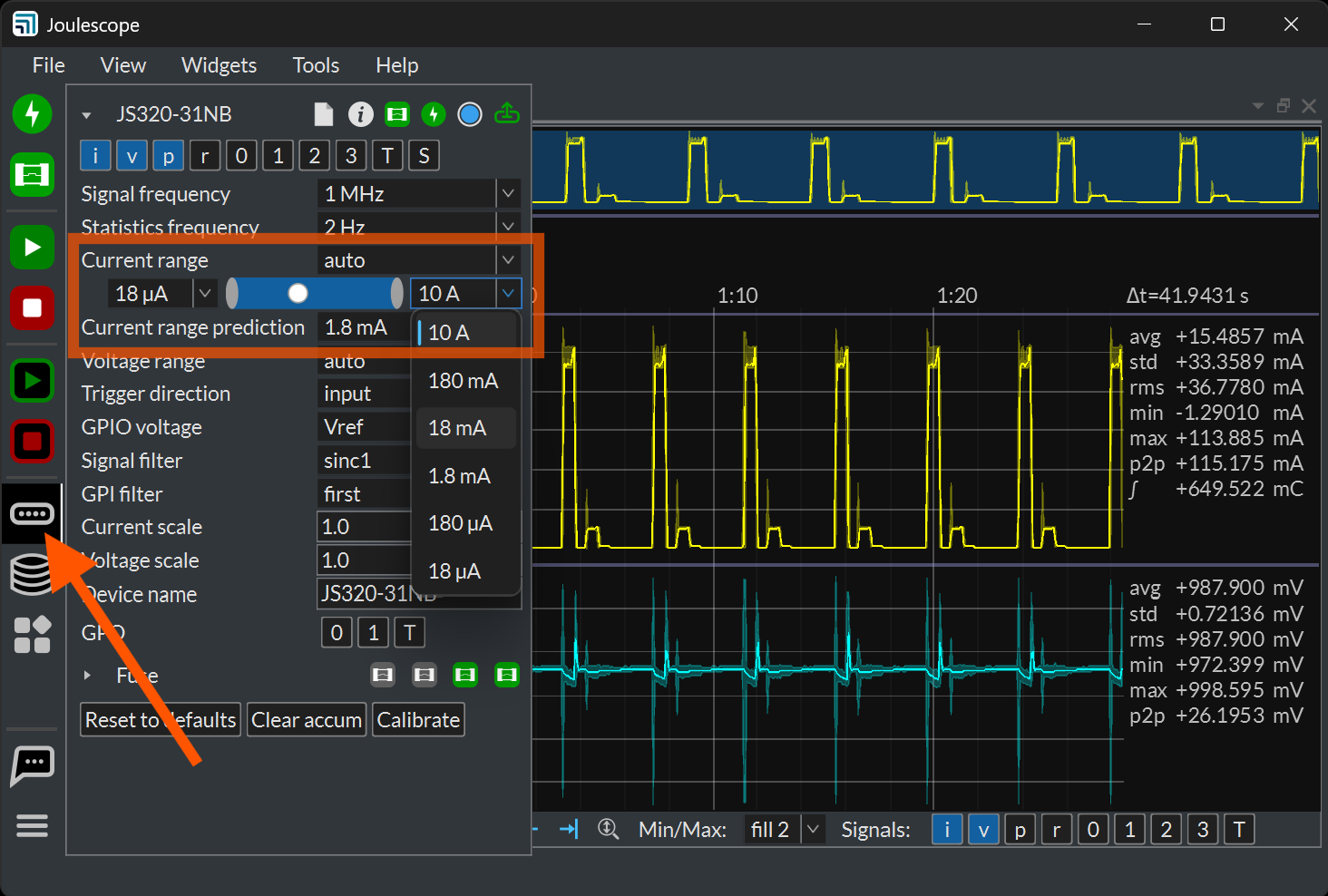
Current range selects
autofor autoranging.The slider below sets the current range limits: the most sensitive range on the left and the maximum current range on the right.
Current range prediction sets the predicted current range.
Scripts use these settings:
Topic |
Meaning |
Default |
|---|---|---|
|
Current range mode: |
|
|
Maximum current range (least sensitive). |
0 (10 A) |
|
Predicted current range on overflow, 0 = off. |
0 (off) |
|
Minimum current range (most sensitive). |
5 (18 µA) |
All range values use the index from Section 7.1.2. Note that
min and max refer to the range index, not to current. s/i/range/min is
the least sensitive range and therefore sets the maximum current.
7.1.6.1. Maximum current range#
The maximum current range, s/i/range/min, limits the least sensitive range
that the autoranger may select. Set it to the smallest range that still
covers the true peak current of the target.
Too high: no measurement error, but overflow transitions jump further than needed.
Too low: currents that exceed five times the range clip, which causes significantly increased inaccuracies.
When the target peak current is unknown, leave it at 10 A.
When the maximum current range is set to anything other than 10 A, the JS320 can measure currents up to five times the range. The JS320 measures the maximum current range with a dedicated ADC input that omits the 5× gain stage of the other current inputs. However, burden voltage increases beyond the specified value. The actual burden voltage is approximately:
When setting the maximum current range, ensure that the waveform never exceeds five times the range when viewed at the full 1 MHz sample rate. The JS320 does contain a soft-fuse feature for each current range to help prevent damage to the instrument if you select too low of a maximum current range. See Section 10.
7.1.6.2. Minimum current range#
Leave the minimum current range, s/i/range/max, at the default 18 µA.
Change it only when the target is affected by the higher input impedance
of the most sensitive ranges, or when the autoranger repeatedly bounces out
of the most sensitive range. The most common reason is a connection to a
DC-DC switching converter with inadequate upstream bulk capacitance.
7.1.6.3. Predicted current range setting#
Set the predicted current range, s/i/range/predict, to the range that
covers the typical short current peaks of the target, such as radio transmit
or receive events. Larger excursions, such as motor or inrush current, still
reach the maximum current range without clipping. 0 turns prediction off.
7.1.6.4. Selecting values#
Consider a Bluetooth product that wakes to measure a sensor at 100 µA and less frequently communicates over RF at 1 mA. If the current never exceeds 9 mA, five times the 1.8 mA range, use:
Maximum current range
s/i/range/min = 3(1.8 mA).Predicted current range
s/i/range/predict = 4(180 µA).
At 9 mA, the burden voltage is approximately 100 mV. If the RF instead takes 10 mA, use:
Maximum current range
s/i/range/min = 2(18 mA).Predicted current range
s/i/range/predict = 4(180 µA).
Select these values:
Statically from the target’s known current profile. For test systems, configure a default for the test bench with per-test or per-capture overrides.
Adaptively by capturing with the default settings, analyzing the peak current distribution, and then selecting the predicted current range to cover the frequent peaks and the maximum current range to cover the largest peak. This analysis is well suited to automated testing.
7.1.7. Isolating Events#
When you investigate brief or intermittent events in your target, it can be hard to tell an event in the target from the effect of Joulescope autoranging. The easiest way to separate them is to select a fixed, manual current range: the most sensitive range that is greater than the maximum current of your target. The JS320 then measures with the precision of that range at the full 1 MHz sample rate, without any autoranging. Any event that you observe is not caused by autoranging, and autoranging cannot affect your target device in any way.
You give up dynamic range, but investigations like this rarely need it. When you finish the investigation, return to autoranging for the best accuracy over the full range that your target may need.
In the Joulescope UI, select the range in the Current range setting of
the Device Control widget. Select auto to resume autoranging. From a
script, select the range, then the manual mode:
d.publish(f'{device}/s/i/range/select', '18 mA')
d.publish(f'{device}/s/i/range/mode', 'manual')
7.1.8. Enable current measurement#
When unpowered, the JS320 disconnects Current + from Current - using
a MOSFET, as does the JS220. The Joulescope UI enables current flow when it
opens the JS320. The host driver does not, so scripts must publish
s/i/range/mode = auto.
Two open modes determine the initial instrument state:
defaults: Reset the instrument to power-on defaults. This disconnects the current path. Use this mode with explicit configuration for repeatable automated tests.restore: Adopt the existing instrument state. Use this mode to keep the target powered across multiple open and close cycles.
An overcurrent soft fuse event also disconnects the current path.
7.1.9. Configure autoranging from a script#
Using pyjoulescope_driver, see the
Joulescope Driver documentation:
from pyjoulescope_driver import Driver

with Driver() as d:
    device = d.device_paths()[0]
    d.open(device, mode='defaults')
    d.publish(f'{device}/s/i/range/min', 2)        # maximum current range: 18 mA
    d.publish(f'{device}/s/i/range/predict', 4)    # predicted range: 180 µA
    d.publish(f'{device}/s/i/range/mode', 'auto')  # connect & autorange
    # ... capture ...
    d.close(device)
The JS320 advertises its full parameter set, including descriptions, defaults, and options:
pip install pyjoulescope_driver
python -m pyjoulescope_driver metadata --out js320.html
The --out extension selects the format: .html, .json, or .yaml.
7.2. Voltmeter#
The voltmeter measures the voltage between Voltage + and Voltage -. The voltmeter scales the input voltage, and uses an analog-to-digital converter (ADC) to digitize the value. The Joulescope instrument sends the voltage samples, along with the current samples, to the host computer. The software applies the calibration to convert from ADC values to actual voltage.
The voltmeter has two different ranges, and you can manually select the best range for your application. The 2V range provides higher resolution for smaller voltages, while the 15V range allows for larger voltage measurements.
The voltmeter intentionally omits the pull resistors to ground, typically 1 MΩ to 10 MΩ for most multimeters and oscilloscopes. However, Voltage + and Voltage - will float when unconnected. The voltmeter measurement is only valid once Voltage + and Voltage - are both connected to within ±15V of the Current + terminal. See Section 7.5 for more detail.
7.3. Host Computer#
The Joulescope instrument requires a host computer to operate. The Joulescope instrument sends 2 million current and voltage samples per second immediately to the host computer over USB. Unlike traditional oscilloscopes, a Joulescope is always capturing data. The terms “trigger” and “sample buffer” do not fully apply to the Joulescope device, since all sample data arrives at the host computer. The Joulescope User Interface (UI) temporarily stores capture data in a circular buffer. The UI allows you to adjust the buffer size to use your host computer’s RAM. Joulescope can also record to a file, and the capture size is only limited by your computer’s available storage on your hard disk drive or solid-state drive.
The Joulescope host software Is open-source. The pyjoulescope “driver” communicates with the appropriate operating system USB driver. Joulescopes use Microsoft’s WinUSB on Windows, which is included by default with the Windows operating system. On Linux and macOS, Joulescope uses the popular, open-source libusb driver. The pyjoulescope driver provides an easy-to-use scripting environment. You can also use the driver to build integrated applications, such as the Joulescope UI, that use the Joulescope instrument data.
7.4. Power, Energy, Charge, and Statistics#
Joulescopes only measure current and voltage. The Joulescope software uses math to compute the power, energy, and charge. Power is the current multiplied by the voltage:
P = V * I = V² / R = I² * R
Energy is the integral of power over time.
When we talk about energy, we often mean the energy consumed over a specific time interval, which is the definite integral:
The Joulescope host software performs the discrete-time Euler integration shown to the right. The Joulescope software carefully manages the numerical precision to ensure that it computes energy correctly. IEEE double-precision floating-point numbers do not provide sufficient precision.
Charge is the integral of current over time.
Charge and energy are mathematically similar. Both voltage and current contribute to energy, but only current contributes to charge.
7.5. High impedance / low leakage#
Joulescope measures currents at nanoamp resolutions and accuracies. Many contemporary devices have input impedances of 1 MΩ to 10 MΩ, which is not good enough. At 3.3V, a 10 MΩ load draws:
3.3V / 10 MΩ = 330 nA
Joulescope features a combined input impedance and leakage current of approximately 1 GΩ. This high input impedance allows Joulescope to make accurate and precise low current measurements.
7.6. Electrical isolation#
The sensor side of Joulescope is electrically isolated from the host computer. This isolation allows you to insert Joulescope into your test system without worrying about ground issues, including ground loops and ground noise. The JS320 sensor-side isolated ground is referenced to Current +.