# Ground loops
A ground loop forms whenever ground connections make a closed path. Ground
loops cause noisy measurements, unexpected target behavior and, with a
current meter, current that bypasses the meter entirely. This page explains
how ground loops form, the problems they cause, and how to avoid them.
## What a ground loop is
Most equipment connects its signal ground to something else: a USB cable
connects a device’s ground to the computer’s ground, and a mains-powered bench
supply, oscilloscope or desktop computer often connects its ground to
protective earth through the power cord. When two connections link the same
two points by different routes, the result is a loop.
[Fig. 5](#theory-ground-loop-figure) shows a common example. A computer
connects through USB to a Joulescope and to a debugger. The Joulescope GPIO
connects to the target to mark firmware activity, and the debugger connects
to the target to program it. Both connections include ground, so the ground
path forms a loop: from the computer, through the Joulescope, through the
target, through the debugger and back to the computer.
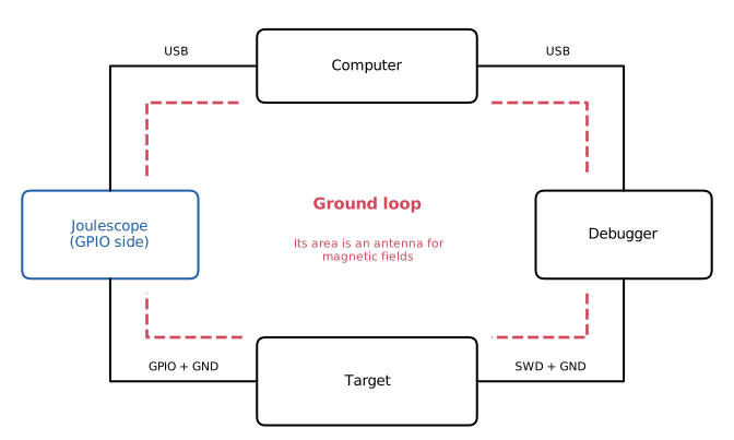
A ground loop formed by the computer, the Joulescope GPIO, the target and
the debugger.
Other common loops include:
* A target powered from a bench supply with an earthed power cord, and
connected to a desktop computer that is also earthed.
* A development board powered from USB by the same computer that the
Joulescope or debugger uses.
* An oscilloscope probe ground clip connected to the target, with the
oscilloscope earthed through its power cord.
Joulescope’s current and voltage terminals are electrically isolated from
USB ground, so they do not form a ground loop with the computer. The GPIO
and trigger connections are referenced to USB ground, so connecting them to
your target connects the target’s ground to the computer’s ground. See the
Electrical Isolation chapter of your instrument’s user’s guide, for example
[the JS320 User’s Guide](https://docs.joulescope.com/en/products/js320/guide/isolation.md#js320-electrical-isolation).
## The problems
### Ground is not one voltage
We often treat ground as a single voltage, 0 V, everywhere in the circuit.
Real wires have resistance, so any current flowing through a ground
conductor creates a voltage difference along it. For example, 100 mA flowing
through 0.1 Ω of cable and connector resistance creates a 10 mV difference
between its two ends.
In a ground loop, current from one piece of equipment can flow through the
ground of another. The grounds at different points in the loop are then at
slightly different voltages, and that difference changes as the current
changes. Analog-to-digital converter readings shift, logic thresholds move,
and voltage measurements include the ground difference. These effects can
look like unusual or intermittent target behavior.
### Noise pickup
A loop of wire is a one-turn coil, which is an antenna for magnetic fields.
A changing magnetic field through the loop induces a voltage around it,
proportional to the area of the loop and how fast the field changes. Mains
wiring, transformers, motors and switching power supplies all create
changing magnetic fields. The ground loop has very low resistance, so even
a small induced voltage drives a noticeable current around it. If the loop
includes the Joulescope’s current path, the Joulescope measures that current
as if the target consumed it.
Power supplies also inject current into ground loops directly. Switching
power supplies, such as laptop chargers, use small capacitors between the
mains and their output to reduce radio interference. When the charger has
no earth connection, these capacitors leak a small current at the mains
frequency into anything connected to the computer’s ground. The current is
harmless to people, but can be tens of microamps, which is large compared to
the sleep current of a low-power target.
A common symptom of either problem is a 50 Hz or 60 Hz signal in low-current
measurements. If this signal disappears when you run a laptop from its
battery or disconnect a piece of equipment, suspect a ground loop.
### Alternate return paths
The Joulescope measures only the current that flows between its **Current +**
and **Current −** terminals. For an accurate measurement, all of the
target’s current must flow through the Joulescope. A ground loop can
provide another path, so that some of the current returns to the supply
without passing through the Joulescope.
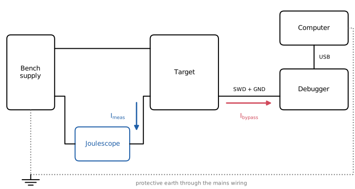
With the Joulescope in the ground wire, the debugger, computer and
protective earth form a second return path. Current that takes it is not
measured.
[Fig. 6](#theory-ground-return-path-figure) shows a Joulescope measuring
current in the ground wire, called low-side current sensing. The target’s
return current can flow through the Joulescope, or through the debugger’s
ground, the computer and protective earth back to the supply. The current
divides between the two paths in inverse proportion to their resistance.
The Joulescope uses shunt resistors up to about 1 kΩ to measure small
currents, while the ground path may be well under 1 Ω. At low currents,
nearly all of the current bypasses the Joulescope.
The same applies to the supply side. If the target can also receive power
from another source, such as a development board’s USB connector, a debugger
that supplies target power, or a serial adapter that back-powers the target
(see [Leakage current](https://docs.joulescope.com/en/theory/leakage.md#theory-leakage)), that current does not flow through the
Joulescope.
For the best measurement, the Joulescope must see the entire supply and
return path of the target’s current. Every path by which current reaches
the target must pass through the Joulescope, and with low-side sensing, so
must every path by which it returns.
## Avoiding ground loops
* Measure current on the supply (+) wire, called high-side current sensing,
as shown in the How to Connect chapter of your instrument’s user’s guide,
for example [the JS320 User’s Guide](https://docs.joulescope.com/en/products/js320/guide/connect.md#js320-measure-power-supply-provided). Ground connections from other
equipment then cannot bypass the Joulescope.
* Power the target only through the Joulescope. Remove or disable other
power sources, such as USB power on development boards and target power
from debuggers.
* Disconnect debuggers, serial adapters, logic analyzers and oscilloscope
probes that you do not need during the measurement. Where you need them,
use a USB isolator or isolated adapter to break the loop.
* Connect the Joulescope GPIO only when you need them, and remember that the
GPIO ground connects the target to the computer.
* Power the target from a battery or a supply without an earth connection.
* Run a laptop from its battery to check whether its charger adds noise.
* Keep the loops you cannot avoid small: twist each supply and return wire
pair together, and route cables together rather than in separate
directions.