# Leakage current
You put your target into its lowest power sleep mode and measure 150 µA
instead of the 2 µA in the microcontroller datasheet. Then you unplug the
debugger, and the current drops to 3 µA. The difference is leakage current:
current that flows through the other equipment connected to your target.
This page explains what leakage current is, which way it flows, and how to
keep it out of your measurements.
## What leakage current is
Every input connected to your circuit draws some current. An ideal digital
or analog input would draw none, so connecting it would not change the
circuit. Real inputs draw current through:
* the input resistance of the equipment, often 1 MΩ or 10 MΩ for test
equipment,
* pull-up and pull-down resistors, which hold a signal at a known level when
nothing drives it,
* the bias current of amplifiers and the leakage of transistors,
* electrostatic discharge (ESD) protection diodes, which conduct when a pin
is above its supply or below ground, and
* output drivers, which actively drive a signal high or low.
Ohm’s Law gives the current through a resistance:
$$
I = \frac{V}{R}
$$
At 3.3 V, a 1 MΩ input draws 3.3 µA, a 100 kΩ input draws 33 µA, and a 10 kΩ
pull-up draws 330 µA. Older or larger devices with milliamps of sleep current
barely notice these values. A modern microcontroller that sleeps at 1 µA, or
a wireless sensor designed to run for years on a coin cell, can easily draw
less than the equipment connected to it.
Typical values for common equipment at 3.3 V:
| Connection | Typical input | Typical current |
|------------------------------|--------------------|-----------------------------|
| Powered CMOS digital input | Transistor leakage | nA to 1 µA |
| Oscilloscope with 10x probe | 10 MΩ | 0.33 µA |
| Oscilloscope 1 MΩ input | 1 MΩ | 3.3 µA |
| Logic analyzer input | 100 kΩ to 1 MΩ | 3.3 µA to 33 µA per channel |
| Debugger signal with pull-up | 10 kΩ to 100 kΩ | 33 µA to 330 µA per pin |
| USB-to-UART adapter output | Driver | Up to mA |
These are examples only. Check the datasheet of your equipment, and
remember that a logic analyzer with 8 channels connected has 8 inputs.
## Which way it flows
Leakage current can flow out of your target or into it, and the two
directions affect your measurement differently.
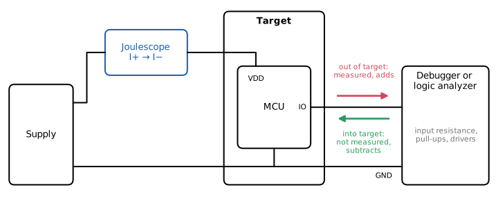
Leakage between a target IO pin and connected equipment. Current that
leaves the target came through the Joulescope. Current that enters the
target powers it without passing through the Joulescope.
Out of the target
: When the target drives a pin high, current flows from the target supply,
through the pin, and into the input resistance or pull-down of the
connected equipment. This current flows through the Joulescope, so the
Joulescope correctly measures it as part of the target’s consumption.
However, it is consumption that your product does not have in the field,
without the equipment connected.
Into the target
: When the connected equipment drives a pin high, or pulls it up to its own
supply, current flows into the target. If the target pin is an input or
the target is asleep, this current can flow through the pin’s ESD diode
into the target’s supply rail. The equipment then powers part of the
target, which is called back-powering or phantom powering. This current
does not flow through the Joulescope, so the measured current is lower
than the real consumption, and can even be negative. Back-powering can
also keep a target partly running when you expect it to be off.
Connected equipment can also increase the target’s own consumption. A
digital input held between low and high, for example by a weak pull-up
fighting a weak pull-down, turns on both transistors of the input stage at
once. The target then draws current from its own supply, often far more
than the leakage itself. Many microcontrollers also keep their debug logic
powered while a debugger is attached, which prevents the deepest sleep
modes until the next power cycle.
Leakage current that returns through a ground connection that bypasses the
Joulescope causes further errors. See [Ground loops](https://docs.joulescope.com/en/theory/ground_loops.md#theory-ground-loops).
## Joulescope’s own leakage
Joulescope instruments are designed for very low leakage on all of their
inputs:
* The current and voltage terminals are electrically isolated from USB
ground. The voltage inputs have very high input impedance and do not use
the 1 MΩ or 10 MΩ input resistance common in other instruments, which would
draw meaningful current from a low-power target.
* The general purpose inputs (GPI) have very low input leakage, so you can
connect them to target signals to mark firmware activity. However, the
GPIO are referenced to USB ground, not isolated. Connecting them also
connects your target’s ground to the computer’s ground through the
Joulescope. See [Ground loops](https://docs.joulescope.com/en/theory/ground_loops.md#theory-ground-loops).
For the leakage specifications, see your instrument’s datasheet, available
from [Products](https://docs.joulescope.com/en/products/index.md). For GPIO usage, see the GPI & GPO chapter of
your instrument’s user’s guide, for example [the JS320 User’s Guide](https://docs.joulescope.com/en/products/js320/guide/gpio.md#js320-gpi-gpo).
## Leakage inside the target
Components on your target leak too. Capacitors, especially electrolytic and
tantalum types, conduct a small current. Diodes conduct a small reverse
current. A resistive divider that monitors the battery voltage draws current
continuously. Unlike the equipment connected for testing, these are part of
your product, and your measurement should include them. Joulescope measures
them as part of the target’s consumption.
## Measuring without leakage
To measure the current your product draws in the field:
1. Measure with only the Joulescope connected, in the configuration that you
ship. Use this as your baseline.
2. Add one piece of equipment at a time and watch for a change. A debugger,
logic analyzer, oscilloscope or serial adapter that changes the sleep
current is leaking.
3. Physically disconnect the debugger, then power cycle the target, before
measuring sleep current. Closing the debug session is often not enough,
because the debugger’s pull-ups and drivers stay connected and the
target’s debug logic may stay powered.
4. Disconnect serial adapters, or make sure they cannot drive a target pin
that is unpowered or in sleep.
5. Use the Joulescope GPI, rather than a logic analyzer, to observe firmware
activity. Connect **Vref** to the target supply so the logic levels
match.
6. Configure unused microcontroller pins in firmware. Do not leave inputs
floating, as they can drift between low and high.