
6. How to Connect Your Joulescope#
The Joulescope JS220 has flexible connections that allow for a wide variety of measurements. This section describes some common test scenarios.
The Joulescope JS220 sensor provides four connections: Voltage +, Voltage -, Current + and Current -. Many test setups also include a power source that provides power and a target device under test that consumes power. We will use the following conventions for this section:
Label |
Description |
|---|---|
V+ |
JS220 voltage + connection |
V- |
JS220 voltage – connection |
I+ |
JS220 current + connection |
I- |
JS220 current – connection |
PS+ |
Power source voltage + connection |
PS- |
Power source voltage – connection |
T+ |
Target device under test voltage + connection |
T- |
Target device under test voltage – connection |
The previous-generation Joulescope JS110 had connections IN+, IN-, OUT+, and OUT-. The following table maps JS110 connections to JS220 connections:
JS110 |
JS220 |
|---|---|
IN+ |
V+ and I+ |
IN- |
V- |
OUT+ |
I- |
OUT- |
V- |
Note that the JS220 provides more flexibility by separating V+ and I+.
6.1. Measure only current (ammeter)#
The Joulescope JS220 features independent current and voltage channels. You can use your Joulescope JS220 to measure the current through any wire. The JS220 will also compute total charge, the integral of current.
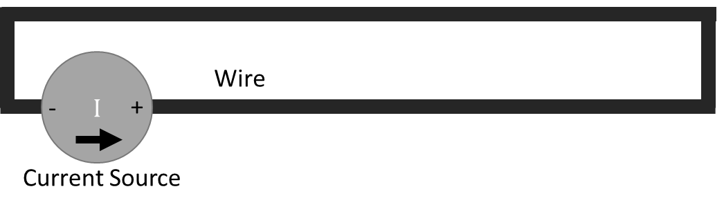
The following figure shows a simple current source with a wire. The current source polarity and arrow are for convention only, and current can flow in both directions.
Simply insert the JS220 inline:
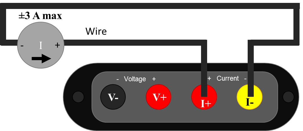
Since your JS220 can measure current flowing in either positive or negative direction, the current flow direction indicator is for convention only. If connected in the opposite direction, the measurement polarity (sign) is reversed. When connecting your JS220 like this, ensure that the current source does not exceed the Joulescope JS220 limit of ±3 A.
During normal operation, the JS220 is designed to keep the voltage at I+ almost equal to the voltage I-. The JS220 uses a resistor to sense the current flowing between I+ and I-, but it limits the shunt resistor voltage to 20 mV maximum, at least for all current under 2 A.
When not connected, you will observe random voltage measurement values that may change over time. The JS220 has extremely high input impedance on V+ and V-. Most test instruments add a known resistance, often 1 MΩ or 10 MΩ, that pulls V+ to V-. The JS220 focuses on low-power measurement, and such a resistor would consume meaningful current. The drawback is that unconnected voltage measurements are affected by nearby electromagnetic fields and the input bias currents of the JS220’s input stage opamps. To eliminate fluctuating voltage readings while using the JS220 as an ammeter, connect I+ to both V+ and V-.
6.2. Measure only voltage (voltmeter)#
The Joulescope JS220 features independent current and voltage channels. You can use your Joulescope JS220 as a one channel, high-impedance, isolated oscilloscope.
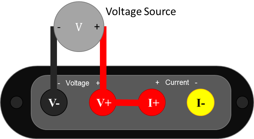
Note the extra connection between V+ and I+. With the standard binding post front panel, you can insert a short length of wire to make this connection. The V- and V+ signals must remain within ±15 V of I+ to measure correctly. The easiest way to ensure this condition is to connect I+ and V+ as shown. Also ensure that the JS220 Current Range is set to anything other than off. Unlike most test equipment, the voltage inputs are completely floating and isolated, so you need to make this connection.
6.3. Measure power supply provided#
The JS220 can measure the current, voltage, power, charge, and energy provided to a target device under test by a power source. A typical system consists of a power source and a target device under test.
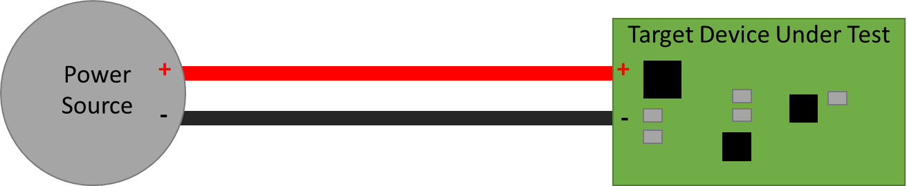
The power source can be anything that provides electricity including a battery, battery pack, rechargeable battery, bench power supply, mains wall adapter, USB, and power regulators.
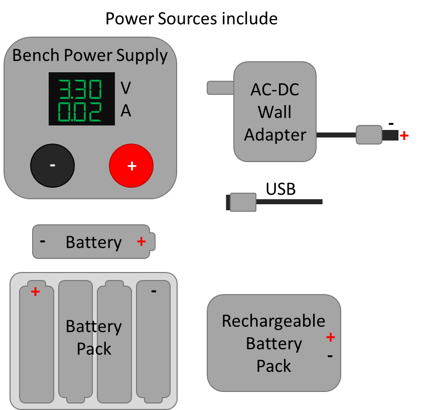
The target device under test can include product prototypes, custom hardware under development, development boards, systems, and subsystems.
The easiest way to connect your JS220 is as an ammeter measuring current in the + wire and as a voltmeter across the power source PS+ and PS-, like this:
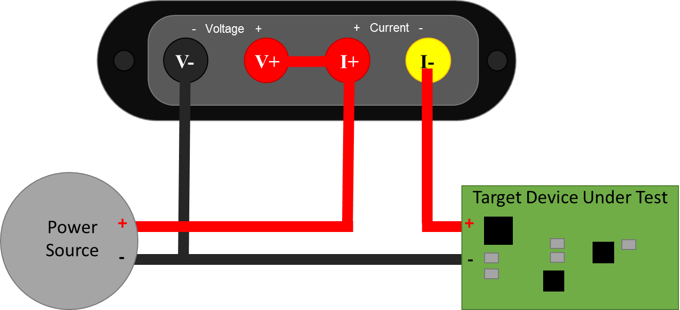
Note that the V- wire is connected to PS- and T-. It does not connect to PS+. This setup configures the Joulescope JS220 in high-side current sense configuration.
If you are familiar with the previous-generation Joulescope JS110, this configuration is the exact same as connecting IN+ to PS+, IN- to PS-, OUT+ to T+, and OUT- to T-. The FP02-BNA front panel provides the JS220 with the exact same connections as the JS110.
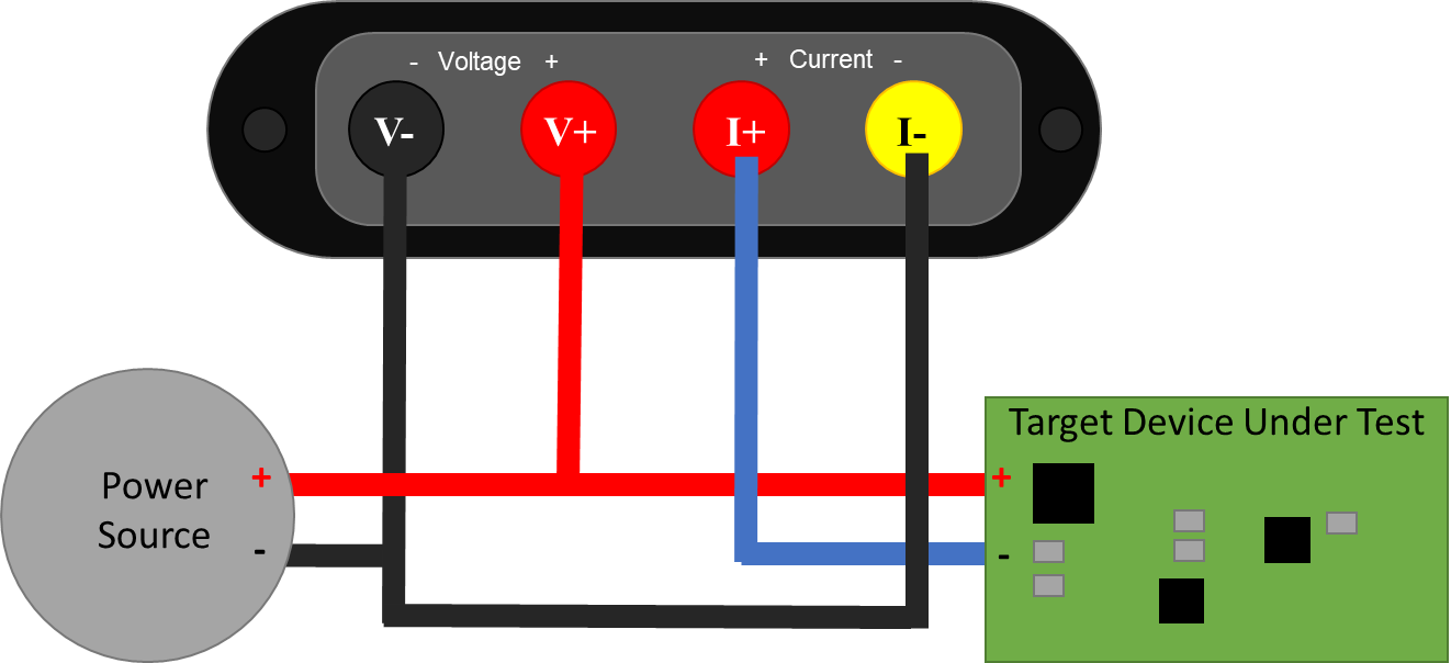
The JS220 can alternatively be used to measure current on the low-side wire connected to PS-.
6.4. Measure target device consumption#
The JS220 can measure the current, voltage, power, charge, and energy consumed by a target device. The JS220 and wires all have resistance (impedance). When current flows, this resistance causes a voltage drop according to Ohm’s Law: V = I * R. While this energy is provided by the power source, it is consumed by the connections between the power source and the target device under test. This loss should not be included in the measurement for target consumption. The JS220 is specifically designed to enable more accurate, 4-wire Kelvin-connection measurements:
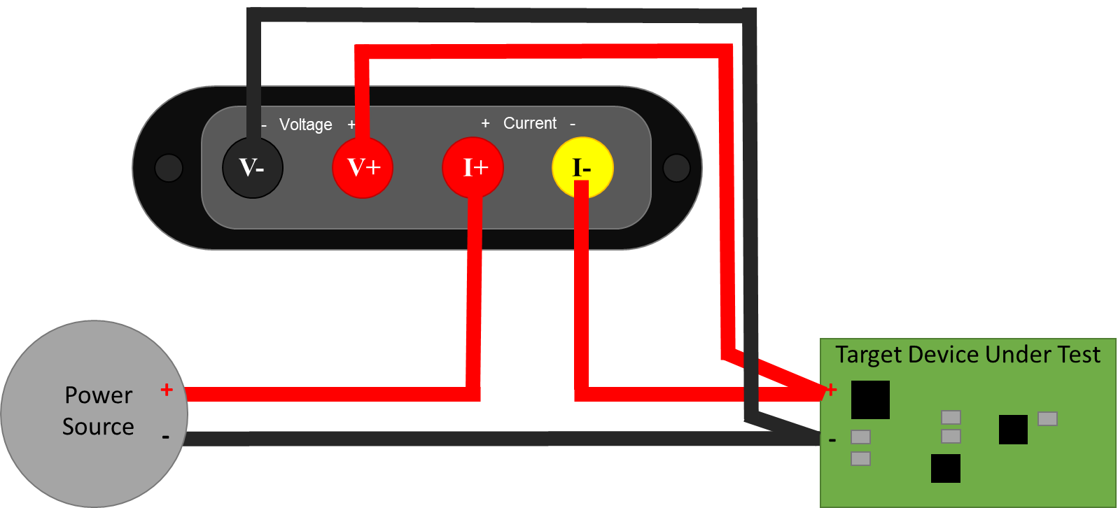
To minimize noise pickup, you want to minimize the loop area. The easiest way to do this is twist the insulated + and – wires together from PS+ and PS- all the way to T+ and T-, like this

Just before connecting to the T+, connect the JS220, connecting the additional wires to the JS220 I+ and I- together. Finally, twist the insulated V+ and V- wires together.
Shorter wires result in both lower resistive voltage losses and lower noise pickup. However, for applications where the target device contains an RF transmitter, you do not want the cables too short. You want to ensure that the JS220 does not become part of the antenna. A good rule of thumb is that you should locate all test equipment one wavelength away from the RF transmitter. One wavelength is approximately 33 cm at 915 MHz and 12 cm at 2.4 GHz.
6.5. Measure subsystem consumption#
The JS220 can measure the current, voltage, power, charge, and energy consumed by subsystem on the target device under test. Many devices and prototype boards have jumpers to simplify current measurement in system. However, some hardware devices require the user to remove a resistor or cut a printed circuit board trace to measure the subsystem current consumption. In either case, you want to connect the JS220 as an ammeter inline with the power source to the subsystem to measure current. The JS220 will also compute charge, the integral of current.
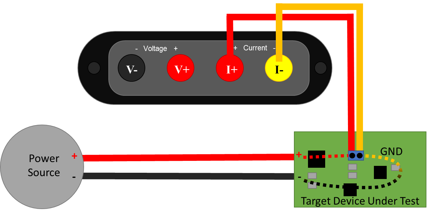
For voltage, power, and energy, also connect the JS220 voltmeter:
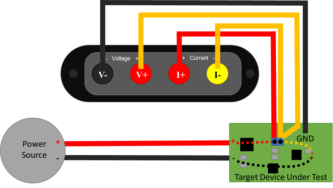
This connection recommendation shows a Kelvin-style 4-wire connection, which helps improve accuracy and minimize noise pickup. Connect the JS220 using two wire pairs, one to measure current and one to measure voltage. Twist the insulated V+ and V- wires together and the I+ and I- wires together to further reduce noise pickup. For less accuracy and perhaps a quicker setup time, connect V+ to I+ and V- to PS-.
6.6. Measure higher voltages#
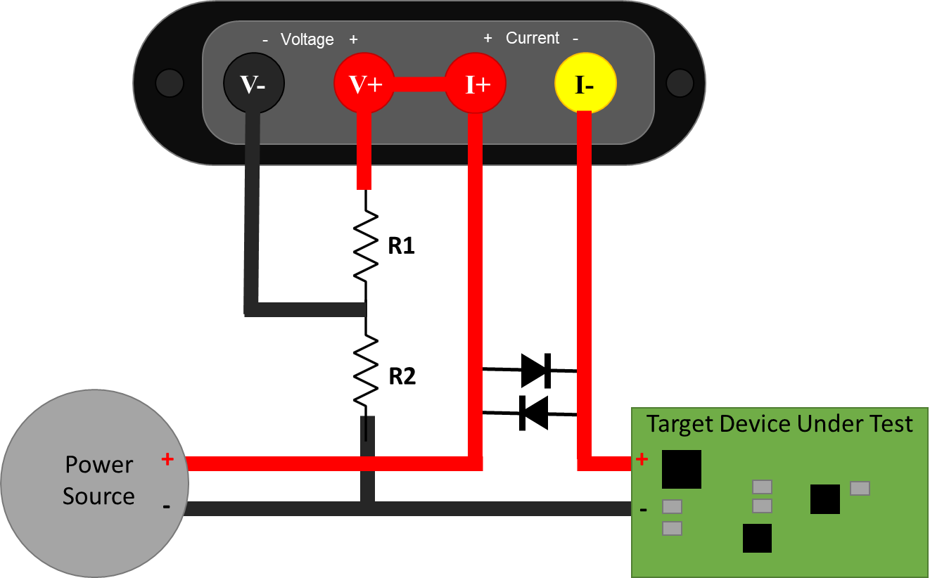
If your system can tolerate additional leakage current on the supply side, then you can use a simple resistive divider to measure higher voltages.
Warning
The voltage from I+ to I- must never exceed ±20 V. While the Joulescope is operating, this voltage is very small. However, when the JS220 is unpowered, a fuse engages, or you use the disconnect target power feature, then the voltage across I+ to I- will be the full power supply voltage. We recommend adding the diodes as shown to prevent damaging your Joulescope in these conditions. Ensure that the diodes are rated for the full current consumed by the target device under test.
The actual voltage as a function of the measured voltage is:
You need to select values for R₁ and R₂ that keep VMEASURED within ±14.5 V, keep leakage current low enough, and preserve measurement bandwidth. The RC filter combination limits the measurement bandwidth:
Leakage current is:
Typical V- input capacitance is on the order of 10 pF, so R₁ = R₂ = 1 MΩ gives approximately 16 kHz of measurement bandwidth and ±29 V of range. At 29 V, the leakage current is 14.5 µA. This additional leakage current comes from the power source, but it is not measured by the JS220.
In the Joulescope UI, you can set the Voltage scale in the Device control widget to adjust the displayed values to account for the voltage divider.
Ensure that V-, V+, I+, and I- are always within ±48 V of USB ground.
You can consider an active buffer solution if your system cannot tolerate the leakage current to give the desired measurement bandwidth.